CopperCAM
CopperCAM
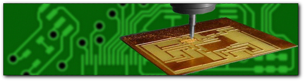
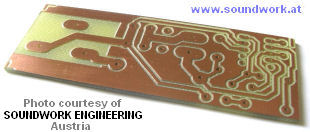
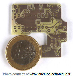
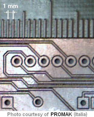
ENGRAVING, DRILLING, CUTTING
PRINTED CIRCUIT BOARD PROTOTYPES
SIMPLE OR DOUBLE-SIDED
CopperCAM is an application for managing isolation engraving, drilling and cutting printed-circuit board prototypes. It does not integrate the direct drive of a CNC milling machine, but simply outputs files that can be loaded and used by external driver software, or data to be sent to the machine. Its major functions are as follows:
- Native 32 bits program for Windows 2000 / 2003-S / XP / Vista / 7 / 8 / 10 / 11
- Import of Gerber & Excellon files, with automatic or manual alignment
- Reading Gerber RS274-X format with macros, polygon surfaces and negative polarity traces
- Management of 4 circuit layers, plus drills, plus cut-out contours, plus centering holes
- Real-time display of equipotential paths through layers
- Automatic calculation of isolation contours, simple or multiple
- Extended isolation around pads, automatic clearance with hatches
- Roughing hatches with a large-diameter tool, finishing in corners with the engraving tool
- Manual modification of isolation contours (deletion or addition with auto-snap)
- Enforcement of isolation between very close pads
- Selection of tracks to be engraved at path centre (texts, logos or references)
- Possible drills with boring cycles, reducing the number of tool changes
- Automatic calculation of board contour cut-path, with manual addition of support bridges
- Edition and correction of diaphragms for pads and tracks, one by one or grouped
- Management of a tool library and drilling strategies depending on available cutters
- G-code output, or HPGL, DXF, Isel-NCP, Roland RDGL, etc.
- Fully customisable post-processor output
- Automatic chaining to a machining driver, or output to a
virtual printer driver or a COM / LPT port
CopperCAM process sequence is simple:
- Opening Gerber file containing one circuit layer
- Opening next layers (maximum 4), if any
- Detecting or plotting card cut-out contour
- Opening Excellon file for drillings, if any
- Aligning layers (automatic or manual)
- Plotting tracks that are centerline texts
- Calculating isolation contours
- Hatching zones for removing all the copper
- Checking drill tools and eventual boring cycles
- Sending output data to the driver software or to the machine
Limitations: there are many variations in Gerber and Excellon formats, and especially for units and scaling systems. Therefore CopperCAM cannot guarantee the import of all files and the correct automatic alignment of layers (but you can operate a manual alignment very easily). Ground-planes that are made of hatches of hundreds or thousands of thin tracks may be very long to isolate, the calculation being made track by track. If the CAD software can do it, it is better to output G36/G37 polygon surfaces that are defined by Gerber RS274-X format.
CopperCAM now reads parametric macros (with $ variables, e.g. KiCad's rounded rectangle pads). Prior to the 25 September 2025 version, it only read macros with constants.
Before purchasing a licence, it is wise to try CopperCAM with your usual electronic CAD software, to check its good compatibility. Please contact us, should you have any problems.


ENGRAVING, DRILLING, CUTTING
PRINTED CIRCUIT BOARD PROTOTYPES
SIMPLE OR DOUBLE-SIDED


